
Following up our previous article on DMVPN, we are going to implement another model of DMVPN deployment, DMVPN dual hub single topology. We have prepared the topology below as a guidance.
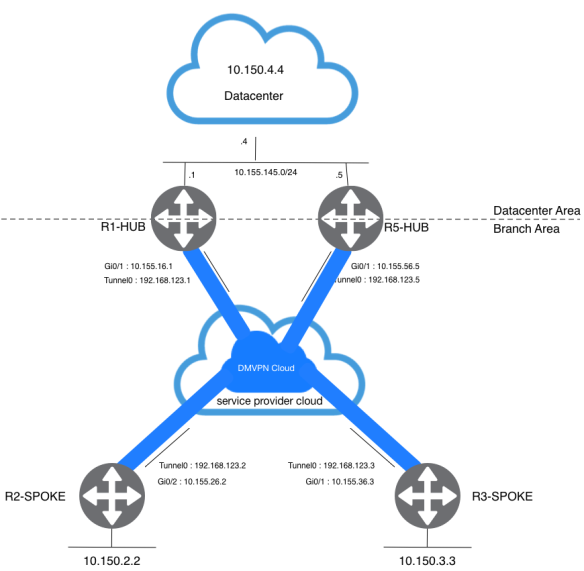
The dual hub with single layout topology is fairly to set up. The idea in this case it to have a single DMPVN “cloud” with all hubs, and all spokes connected to this single subnet (“cloud”). On above topology, you will have two static tunnels from each spoke to the hubs (R1-HUB and R5-HUB). Since the spoke router are routing neighbors with the hub routers over the same mGRE tunnel interface, you cannot use link or interface differences (like metric, cost, delay or bandwidth) to modify the dynamic routing protocol metric toprefer one hub over the other hub when they are both up. If this preference is needed, then you can utilize the routing protocol feature to engineering traffic flow.
Router Configuration
Since we don’t have any major differences on the configuration. We will only show the additional configuration for this purpose. Any full configuration you may refer to my previous post on DMVPN.
R1-HUB
router eigrp 100
 network 10.155.145.1 0.0.0.0
 network 192.168.123.1 0.0.0.0
R5-HUB
crypto isakmp policy 10
 encr aes
 authentication pre-share
 group 14
crypto isakmp key cisco123 address 10.155.0.0
!
!
crypto ipsec transform-set MYTRANSFORMSET esp-aes esp-sha-hmac
 mode tunnel
!
crypto ipsec profile MYPROFILE
 set security-association lifetime seconds 900
 set transform-set MYTRANSFORMSET

interface Tunnel0
 ip address 192.168.123.5 255.255.255.0
 no ip redirects
 ip mtu 1440
 no ip next-hop-self eigrp 100
 no ip split-horizon eigrp 100
 ip nhrp authentication cisco123
 ip nhrp map multicast dynamic
 ip nhrp map 192.168.123.1 10.155.16.1
 ip nhrp map multicast 10.155.16.1
 ip nhrp network-id 1
 ip nhrp nhs 192.168.123.1
 tunnel source GigabitEthernet0/1
 tunnel mode gre multipoint
 tunnel key 12345
 tunnel protection ipsec profile MYPROFILE

 router eigrp 100
 network 10.155.145.5 0.0.0.0
 network 192.168.123.5 0.0.0.0
I did two changes on R1-HUB, remove the loopback IP from EIGRP proceess and put datacenter segment instead. The configuration for R5-HUB is basically the same as the R1-HUB configuration with the appropriate IP address changes. The one main difference is that R5-HUB is also a spoke (or client) of R1-HUB, making R1-HUB the primary hub and R5-HUB the secondary hub.
R2-Spoke
interface Tunnel0
 ip address 192.168.123.2 255.255.255.0
 no ip redirects
 ip mtu 1440
 ip nhrp authentication cisco123
 ip nhrp map multicast dynamic
 ip nhrp map 192.168.123.1 10.155.16.1
 ip nhrp map multicast 10.155.16.1
 ip nhrp map 192.168.123.5 10.155.56.5
 ip nhrp map multicast 10.155.56.5
 ip nhrp network-id 1
 ip nhrp nhs 192.168.123.1
 ip nhrp nhs 192.168.123.5
 tunnel source GigabitEthernet0/2
 tunnel mode gre multipoint
 tunnel key 12345
 tunnel protection ipsec profile MYPROFILE
R3-Spoke
interface Tunnel0
 ip address 192.168.123.3 255.255.255.0
 no ip redirects
 ip mtu 1440
 ip nhrp authentication cisco123
 ip nhrp map multicast dynamic
 ip nhrp map 192.168.123.1 10.155.16.1
 ip nhrp map multicast 10.155.16.1
 ip nhrp map 192.168.123.5 10.155.56.5
 ip nhrp map multicast 10.155.56.5
 ip nhrp network-id 1
 ip nhrp nhs 192.168.123.1
 ip nhrp nhs 192.168.123.5
 tunnel source GigabitEthernet0/1
 tunnel mode gre multipoint
 tunnel key 12345
 tunnel protection ipsec profile MYPROFILE
Remember that by defining the static NHRP mapping and NHS on a spoke router for a hub, you are going to run the dynamic routing protocol over this tunnel. This defines the hub and spoke routing or neighbor network.
Verifications
From the R1-HUB perpective, its peer R5-HUB was discovered through dynamic tunnel. R1-HUB treat R5-HUB as another spoke router because from the R5-HUB perspective, it need to define its “next hop server” statically. From spokes side, it will have two “next hop server using the same tunnel, “tunnel0“.
R1-HUB#show dmvpn
----------------output omitted for brevity-----------------

Interface: Tunnel0, IPv4 NHRP Details
Type:Hub, NHRP Peers:3,

 # Ent  Peer NBMA Addr Peer Tunnel Add State  UpDn Tm Attrb
 ----- --------------- --------------- ----- -------- -----
     1 10.155.26.2       192.168.123.2    UP 18:41:39     D
     1 10.155.36.3       192.168.123.3    UP 18:41:39     D
     1 10.155.56.5       192.168.123.5    UP 17:59:49     D
R5-HUB#sh dmvpn
----------------output omitted for brevity-----------------

Interface: Tunnel0, IPv4 NHRP Details
Type:Hub/Spoke, NHRP Peers:3,

 # Ent  Peer NBMA Addr Peer Tunnel Add State  UpDn Tm Attrb
 ----- --------------- --------------- ----- -------- -----
     1 10.155.16.1       192.168.123.1    UP 18:01:04     S
     1 10.155.26.2       192.168.123.2    UP 18:01:00     D
     1 10.155.36.3       192.168.123.3    UP 18:01:00     D
R2-SPOKE#sh ip nhrp
192.168.123.1/32 via 192.168.123.1
   Tunnel0 created 5d22h, never expire
   Type: static, Flags: used
   NBMA address: 10.155.16.1
192.168.123.5/32 via 192.168.123.5
   Tunnel0 created 2d08h, never expire
   Type: static, Flags: used
   NBMA address: 10.155.56.5
R2-SPOKE#sh ip nhrp nhs
Legend: E=Expecting replies, R=Responding, W=Waiting
Tunnel0:
192.168.123.1  RE priority = 0 cluster = 0
192.168.123.5  RE priority = 0 cluster = 0
On this dual hubs single topology layout, dynamic spoke-to-spoke tunnel is still works. As we demonstrated on earlier article, it will create a spoke-to-spoke dynamic tunnel after we triggered a traffic from one spoke to another.
R2-SPOKE#sh dmvpn
----------------output omitted for brevity-----------------

Interface: Tunnel0, IPv4 NHRP Details
Type:Spoke, NHRP Peers:2,

 # Ent  Peer NBMA Addr Peer Tunnel Add State  UpDn Tm Attrb
 ----- --------------- --------------- ----- -------- -----
     1 10.155.16.1       192.168.123.1    UP    2d06h     S
     1 10.155.56.5       192.168.123.5    UP    1d15h     S
R2-SPOKE#traceroute 10.150.3.3
Type escape sequence to abort.
Tracing the route to 10.150.3.3
VRF info: (vrf in name/id, vrf out name/id)
  1 192.168.123.1 2 msec
    192.168.123.3 3 msec *
R2-SPOKE#traceroute 10.150.3.3
Type escape sequence to abort.
Tracing the route to 10.150.3.3
VRF info: (vrf in name/id, vrf out name/id)
  1 192.168.123.3 4 msec *  1 msec
R2-SPOKE#show dmvpn
----------------output omitted for brevity-----------------

Interface: Tunnel0, IPv4 NHRP Details
Type:Spoke, NHRP Peers:3,

 # Ent  Peer NBMA Addr Peer Tunnel Add State  UpDn Tm Attrb
 ----- --------------- --------------- ----- -------- -----
     1 10.155.16.1       192.168.123.1    UP    2d06h     S
     1 10.155.36.3       192.168.123.3    UP 00:00:10     D
     1 10.155.56.5       192.168.123.5    UP    1d15h     S
After all communications establish, traffic from the spokes to the datacenter will load balance through R1-HUB and R5-HUB. This is a default behaviour since all HUBs using same dmvpn cloud.
R2-SPOKE#sh ip route 10.150.4.4
Routing entry for 10.150.4.4/32
  Known via "eigrp 100", distance 90, metric 27008256, type internal
  Redistributing via eigrp 100
  Last update from 192.168.123.1 on Tunnel0, 00:00:24 ago
  Routing Descriptor Blocks:
  * 192.168.123.5, from 192.168.123.5, 00:00:24 ago, via Tunnel0
      Route metric is 27008256, traffic share count is 1
      Total delay is 55010 microseconds, minimum bandwidth is 100 Kbit
      Reliability 255/255, minimum MTU 1440 bytes
      Loading 43/255, Hops 2
    192.168.123.1, from 192.168.123.1, 00:00:24 ago, via Tunnel0
      Route metric is 27008256, traffic share count is 1
      Total delay is 55010 microseconds, minimum bandwidth is 100 Kbit
      Reliability 255/255, minimum MTU 1440 bytes
      Loading 1/255, Hops 2
R2-SPOKE#sh ip eigrp topology 10.150.4.4 255.255.255.255
EIGRP-IPv4 Topology Entry for AS(100)/ID(10.150.2.2) for 10.150.4.4/32
  State is Passive, Query origin flag is 1, 2 Successor(s), FD is 27008256
  Descriptor Blocks:
  192.168.123.1 (Tunnel0), from 192.168.123.1, Send flag is 0x0
      Composite metric is (27008256/130816), route is Internal
      Vector metric:
        Minimum bandwidth is 100 Kbit
        Total delay is 55010 microseconds
        Reliability is 255/255
        Load is 1/255
        Minimum MTU is 1440
        Hop count is 2
        Originating router is 10.150.4.4
  192.168.123.5 (Tunnel0), from 192.168.123.5, Send flag is 0x0
      Composite metric is (27008256/130816), route is Internal
      Vector metric:
        Minimum bandwidth is 100 Kbit
        Total delay is 55010 microseconds
        Reliability is 255/255
        Load is 43/255
        Minimum MTU is 1440
        Hop count is 2
        Originating router is 10.150.4.4
R2-SPOKE#traceroute
Protocol [ip]:
Target IP address: 10.150.4.4
Source address:
Numeric display [n]:
Timeout in seconds [3]:
Probe count [3]: 4
Minimum Time to Live [1]:
Maximum Time to Live [30]:
Port Number [33434]:
Loose, Strict, Record, Timestamp, Verbose[none]: V
Loose, Strict, Record, Timestamp, Verbose[V]:
Type escape sequence to abort.
Tracing the route to 10.150.4.4
VRF info: (vrf in name/id, vrf out name/id)
  1 192.168.123.1 1 msec
    192.168.123.5 11 msec
    192.168.123.1 3 msec
    192.168.123.5 6 msec
  2 10.155.145.4 1 msec *  1 msec *
Same goes for traffic from datacenter to each spoke, it will load balance through R1-HUB and R5-HUB. When this happens, asymmetric routing or per-packet load balancing across the links to the two hubs and this will lead to another problem, out of order packet delivery.
R4-DATACENTER#sh ip route eigrp
Codes: L - local, C - connected, S - static, R - RIP, M - mobile, B - BGP
       D - EIGRP, EX - EIGRP external, O - OSPF, IA - OSPF inter area
       N1 - OSPF NSSA external type 1, N2 - OSPF NSSA external type 2
       E1 - OSPF external type 1, E2 - OSPF external type 2
       i - IS-IS, su - IS-IS summary, L1 - IS-IS level-1, L2 - IS-IS level-2
       ia - IS-IS inter area, * - candidate default, U - per-user static route
       o - ODR, P - periodic downloaded static route, H - NHRP, l - LISP
       a - application route
       + - replicated route, % - next hop override

Gateway of last resort is not set

      10.0.0.0/8 is variably subnetted, 7 subnets, 2 masks
D        10.150.2.2/32
           [90/27008256] via 10.155.145.5, 1d15h, GigabitEthernet0/2
           [90/27008256] via 10.155.145.1, 1d15h, GigabitEthernet0/2
D        10.150.3.3/32
           [90/27008256] via 10.155.145.5, 1d15h, GigabitEthernet0/2
           [90/27008256] via 10.155.145.1, 1d15h, GigabitEthernet0/2
D     192.168.123.0/24
           [90/26880256] via 10.155.145.5, 1d15h, GigabitEthernet0/2
           [90/26880256] via 10.155.145.1, 1d15h, GigabitEthernet0/2
R4-DATACENTER#sh ip eigrp topology 10.150.2.2 255.255.255.255
EIGRP-IPv4 Topology Entry for AS(100)/ID(10.150.4.4) for 10.150.2.2/32
  State is Passive, Query origin flag is 1, 2 Successor(s), FD is 27008256
  Descriptor Blocks:
  10.155.145.1 (GigabitEthernet0/2), from 10.155.145.1, Send flag is 0x0
      Composite metric is (27008256/27008000), route is Internal
      Vector metric:
        Minimum bandwidth is 100 Kbit
        Total delay is 55010 microseconds
        Reliability is 255/255
        Load is 1/255
        Minimum MTU is 1440
        Hop count is 2
        Originating router is 10.150.2.2
  10.155.145.5 (GigabitEthernet0/2), from 10.155.145.5, Send flag is 0x0
      Composite metric is (27008256/27008000), route is Internal
      Vector metric:
        Minimum bandwidth is 100 Kbit
        Total delay is 55010 microseconds
        Reliability is 255/255
        Load is 58/255
        Minimum MTU is 1440
        Hop count is 2
        Originating router is 10.150.2.2
R4-DATACENTER#traceroute
Protocol [ip]:
Target IP address: 10.150.2.2
Source address:
Numeric display [n]:
Timeout in seconds [3]:
Probe count [3]: 4
Minimum Time to Live [1]:
Maximum Time to Live [30]:
Port Number [33434]:
Loose, Strict, Record, Timestamp, Verbose[none]: V
Loose, Strict, Record, Timestamp, Verbose[V]:
Type escape sequence to abort.
Tracing the route to 10.150.2.2
VRF info: (vrf in name/id, vrf out name/id)
  1 10.155.145.1 1 msec
    10.155.145.5 1 msec
    10.155.145.1 7 msec
    10.155.145.5 1 msec
  2 192.168.123.2 4 msec *  8 msec *
In order to mitigate this behaviour, we will manipulate traffic flow from spokes to datacenter and vice versa. In this experiment, we engineered flow traffic to use R5-HUB as the primary traffic path. We accomplish this using an attribute on the routing protocol level.
ip access-list standard OFFSET-BRANCH
 permit 10.150.2.2
 permit 10.150.3.3
ip access-list standard OFFSET-DC
 permit 10.150.4.4
!
router eigrp 100
 network 10.155.145.1 0.0.0.0
 network 192.168.123.1 0.0.0.0
 offset-list OFFSET-DC out 500 Tunnel0
 offset-list OFFSET-OFFSET-BRANCH out 500 GigabitEthernet0/3
Now let’s verify route information from the spokes and the datacenter. Make sure it uses R5-HUB as the gateway.
R2-SPOKE#sh ip eigrp topology 10.150.4.4 255.255.255.255
EIGRP-IPv4 Topology Entry for AS(100)/ID(10.150.2.2) for 10.150.4.4/32
  State is Passive, Query origin flag is 1, 1 Successor(s), FD is 27008256
  Descriptor Blocks:
  192.168.123.5 (Tunnel0), from 192.168.123.5, Send flag is 0x0
      Composite metric is (27008256/130816), route is Internal
      Vector metric:
        Minimum bandwidth is 100 Kbit
        Total delay is 55010 microseconds
        Reliability is 255/255
        Load is 43/255
        Minimum MTU is 1440
        Hop count is 2
        Originating router is 10.150.4.4
  192.168.123.1 (Tunnel0), from 192.168.123.1, Send flag is 0x0
      Composite metric is (27008756/131316), route is Internal
      Vector metric:
        Minimum bandwidth is 100 Kbit
        Total delay is 55029 microseconds
        Reliability is 255/255
        Load is 1/255
        Minimum MTU is 1440
        Hop count is 2
        Originating router is 10.150.4.4
R2-SPOKE#sh ip route 10.150.4.4
Routing entry for 10.150.4.4/32
  Known via "eigrp 100", distance 90, metric 27008256, type internal
  Redistributing via eigrp 100
  Last update from 192.168.123.5 on Tunnel0, 00:02:10 ago
  Routing Descriptor Blocks:
  * 192.168.123.5, from 192.168.123.5, 00:02:10 ago, via Tunnel0
      Route metric is 27008256, traffic share count is 1
      Total delay is 55010 microseconds, minimum bandwidth is 100 Kbit
      Reliability 255/255, minimum MTU 1440 bytes
      Loading 43/255, Hops 2
R2-SPOKE#traceroute
Protocol [ip]:
Target IP address: 10.150.4.4
Source address:
Numeric display [n]:
Timeout in seconds [3]:
Probe count [3]: 4
Minimum Time to Live [1]:
Maximum Time to Live [30]:
Port Number [33434]:
Loose, Strict, Record, Timestamp, Verbose[none]: V
Loose, Strict, Record, Timestamp, Verbose[V]:
Type escape sequence to abort.
Tracing the route to 10.150.4.4
VRF info: (vrf in name/id, vrf out name/id)
  1 192.168.123.5 4 msec 5 msec 0 msec 3 msec
  2 10.155.145.4 2 msec *  1 msec *
Also verify route information from the datacenter to the spokes. Make sure it uses R5-HUB as the gateway.
R4-DATACENTER#sh ip eigrp topology 10.150.2.2 255.255.255.255
EIGRP-IPv4 Topology Entry for AS(100)/ID(10.150.4.4) for 10.150.2.2/32
  State is Passive, Query origin flag is 1, 1 Successor(s), FD is 27008256
  Descriptor Blocks:
  10.155.145.5 (GigabitEthernet0/2), from 10.155.145.5, Send flag is 0x0
      Composite metric is (27008256/27008000), route is Internal
      Vector metric:
        Minimum bandwidth is 100 Kbit
        Total delay is 55010 microseconds
        Reliability is 255/255
        Load is 58/255
        Minimum MTU is 1440
        Hop count is 2
        Originating router is 10.150.2.2
  10.155.145.1 (GigabitEthernet0/2), from 10.155.145.1, Send flag is 0x0
      Composite metric is (27008756/27008500), route is Internal
      Vector metric:
        Minimum bandwidth is 100 Kbit
        Total delay is 55029 microseconds
        Reliability is 255/255
        Load is 1/255
        Minimum MTU is 1440
        Hop count is 2
        Originating router is 10.150.2.2
R4-DATACENTER#sh ip route 10.150.2.2
Routing entry for 10.150.2.2/32
  Known via "eigrp 100", distance 90, metric 27008256, type internal
  Redistributing via eigrp 100
  Last update from 10.155.145.5 on GigabitEthernet0/2, 00:00:42 ago
  Routing Descriptor Blocks:
  * 10.155.145.5, from 10.155.145.5, 00:00:42 ago, via GigabitEthernet0/2
      Route metric is 27008256, traffic share count is 1
      Total delay is 55010 microseconds, minimum bandwidth is 100 Kbit
      Reliability 255/255, minimum MTU 1440 bytes
      Loading 58/255, Hops 2
R4-DATACENTER#traceroute
Protocol [ip]:
Target IP address: 10.150.2.2
Source address:
Numeric display [n]:
Timeout in seconds [3]:
Probe count [3]: 4
Minimum Time to Live [1]:
Maximum Time to Live [30]:
Port Number [33434]:
Loose, Strict, Record, Timestamp, Verbose[none]: V
Loose, Strict, Record, Timestamp, Verbose[V]:
Type escape sequence to abort.
Tracing the route to 10.150.2.2
VRF info: (vrf in name/id, vrf out name/id)
  1 10.155.145.5 0 msec 1 msec 1 msec 1 msec
  2 192.168.123.2 1 msec *  2 msec *
High Availibility Test
In order to achive a resilience network, high availability is a must on a production network. On the first test, we tried to shut down tunnel0 interface on the R5-HUB so it will force traffic from the spokes through R1-HUB. After we shut down the interface, we could see several time out occurs.
R2-SPOKE#ping 10.150.4.4 repeat 1000
Type escape sequence to abort.
Sending 1000, 100-byte ICMP Echos to 10.150.4.4, timeout is 2 seconds:
!!!!!!!!!!!!!!!!!!!!!!!!!!!!!!!!!!!!!!!!!!!!!!!!!!!!!!!!!!!!!!!!!!!!!!
!!!!!!!!!!!!!!!!!!!!!!!!!!!!!!!!!!!!!!!!!!!!!!!!!!!!!!!!!!!!!......!!!
!!!!!!!!!!!!!!!!!!!!!!!!!!!!!!!!!!!!!!!!!!!!!!!!!!!!!!!!!!!!!!!!!!!!!!
!!!!!!!!!!!!!!!!!!!!!!!!!!!!!!!!!!!!!!!!!!!!!!!!!!!!!!!!!!!!!!!!!!!!!!
!!!!!!!!!!!!!!!!!!!!!!!!!!!!!!!!!!!!!!!!!!!!!!!!!!!!!!!!!!!!!!!!!!!!!!
!!!!!!!*Dec 31 06:09:32.676: %DUAL-5-NBRCHANGE: EIGRP-IPv4 100: Neighbor 192.168.123.5 (Tunnel0) is down: holding time expired!!!!!!!!!!!!!!!!!!!!!!!!!!!!!!!!!!!!!!!!!!!!!!!!!!!!!!!!!!!!!!!
!!!!!!!!!!!!!!!!!!!!!!!!!!!!!!!!!!!!!!!!!!!!!!!!!!!!!!!!!!!!!!!!!!!!!!
!!!!!!!!!!!!!!!!!!!!!!!!!!!!!!!!!!!!!!!!!!!!!!!!!!!!!!!!!!!!!!!!!!!!!!
!!!!!!!!!!!!!!!!!!!!!!!!!!!!!!!!!!!!!!!!!!!!!!!!!!!!!!!!!!!!!!!!!!!!!!
!!!!!!!!!!!!!!!!!!!!!!!!!!!!!!!!!!!!!!!!!!!!!!!!!!!!!!!!!!!!!!!!!!!!!!
!!!!!!!!!!!!!!!!!!!!!!!!!!!!!!!!!!!!!!!!!!!!!!!!!!!!!!!!!!!!!!!!!!!!!!
!!!!!!!!!!!!!!!!!!!!!!!!!!!!!!!!!!!!!!!!!!!!!!!!!!!!!!!!!!!!!!!!!!!!!!
!!!!!!!!!!!!!!!!!!!!!!!!!!!!!!!!!!!!!!!!!!!!!!!!!!!!!!!!!!!!!!!!!!!!!!
!!!!!!!!!!!!!!!!!!!!!!!!!!!!!!!!!!!!!!!!!!!!!!!!!!!!!!!!!!!!!!!!!!!!!!
!!!!!!!!!!!!!!!!!!!!
Success rate is 99 percent (994/1000), round-trip min/avg/max = 1/5/16 ms
On the second test, we tried to bring back interface tunnel0 operational. At the same time we were executed ping command to measure how long tunnel0 takes to be operational.
R2-SPOKE#ping 192.168.123.5 repeat 1000
Type escape sequence to abort.
Sending 1000, 100-byte ICMP Echos to 192.168.123.5, timeout is 2 seconds:
....!!!!!!!!!!!!!!!!!!!!!!!!!!!!!!!!!!!!!!!!!!!!!!!!!!!!!!!!!!!!!!!!!!
!!!!!!!!!!!!!!!!!!!!!!!!!!!!!!!!!!!!!!!!!!!!!!!!!!!!!!!!!!!!!!!!!!!!!!
!!!!!!!!!!!!!!!!!!!!!!!!!!!!!!!!!!!!!!!!!!!!!!!!!!!!!!!!!!!!!!!!!!!!!!
!!!!!!!!!!!!!!!!!!!!!!!!!!!!!!!!!!!!!!!!!!!!!!!!!!!!!!!!!!!!!!!!!!!!!!
!!!!!!!!!!!!!!!!!!!!!!!!!!!!!!!!!!!!!!!!!!!!!!!!!!!!!!!!!!!!!!!!!!!!!!
!!!!!!!!!!!!!!!!!!!!!!!!!!!!!!!!!!!!!!!!!!!!!!!!!!!!!!!!!!!!!!!!!!!!!!
!!!!!!!!!!!!!!!!!!!!!!!!!!!!!!!!!!!!!!!!!!!!!!!!!!!!!!!!!!!!!!!!!!!!!!
!!!!!!!!!!!!!!!!!!!!!!!!!!!!!!!!!!!!!!!!!!!!!!!!!!!!!!!!!!!!!!!!!!!!!!
!!!!!!!!!!!!!!!!!!!!!!!!!!!!!!!!!!!!!!!!!!!!!!!!!!!!!!!!!!!!!!!!!!!!!!
!!!!!!!!!!!!!!!!!!!!!!!!!!!!!!!!!!!!!!!!!!!!!!!!!!!!!!!!!!!!!!!!!!!!!!
!!!!!!!!!!!!!!!!!!!!!!!!!!!!!!!!!!!!!!!!!!!!!!!!!!!!!!!!!!!!!!!!!!!!!!
!!!!!!!!!!!!!!!!!!!!!!!!!!!!!!!!!!!!!!!!!!!!!!!!!!!!!!!!!!!!!!!!!!!!!!
!!!!!!!!!!!!!!!!!!!!!!!!!!!!!!!!!!!!!!!!!!!!!!!!!!!!!!!!!!!!!!!!!!!!!!
!!!!!!!!!!!!!!!!!!!!!!!!!!!!!!!!!!!!!!!!!!!!!!!!!!!!!!!!!!!!!!!!!!!!!!
!!!!!!!!!!!!!!!!!!!!
Success rate is 99 percent (996/1000), round-trip min/avg/max = 1/4/66 ms
R2-SPOKE#ping 10.150.4.4 repeat 6000
Type escape sequence to abort.
Sending 6000, 100-byte ICMP Echos to 10.150.4.4, timeout is 2 seconds:
---------------------output omitted for brevity-----------------------
!!!!!!!!!!!!!!!!!!!!!!!!!!!!!!!!!!!!!!!!!!!!!!!!!!!!!!!!!!!!!!!!!!!!!!
!!!!!!!!!!!!!!!!!!!!!!!!!!!!!!!!!!!!!!!!!!!!!!!
*Dec 31 06:49:08.164: %DUAL-5-NBRCHANGE: EIGRP-IPv4 100: Neighbor 192.168.123.5 (Tunnel0) is up: new adjacency!!!!!!!!!!!!!!!!!!!!!!!
!!!!!!!!!!!!!!!!!!!!!!!!!!!!!!!!!!!!!!!!!!!!!!!!!!!!!!!!!!!!!!!!!!!!!!
---------------------output omitted for brevity-----------------------
Success rate is 100 percent (6000/6000), round-trip min/avg/max = 1/4/66 ms
As you can see from the output above, we are not seeing any packets lost from spokes to datacenter even though it took several time outs on the tunnel0 before it become online.
Contributor:

Ananto Yudi Hendrawan
Network Engineer - CCIE Service Provider #38962, RHCSA, VCP6-DCV
nantoyudi@gmail.com
